Tuesday, September 29, 2009

Frame Relay

Frame Relay is another type of encapsulation in WAN protocol . as you know The others are PPP , HDLC and ATM. PPP and HDLC are leased line protocol but Frame Relay works on Frame Relay .
(Wan Speed : From 2400bps to 45Mbps(T3))
DTE = Data Terminal Equepment
DCE = Data Communication Equepment

Remember these notes about Frame Relay :
  • Frame Relay is a popular WAN protocol that today is instead with VPN and Multi Protocol Lable Switching (MPLS)
  • Frame Relay Task is deliver layer 3 packets between routers.
  • Leased line provides a WAN service between tow points . each router with CSU/DSU on end of this link and installing two-pair(four wire) cable into the building . a dedicated line . if you need more than one link you should order a new link with new devices on end of new link . but in Frame Relay you could have more than one links and WAN services between some points without buy more than one link or buy new devices . in other words Frame Relay is a point-to-point , point-to-multi point and Muti point-to-Multi point wan service with cost advantages than leased line actually Frame Relay can send data to multiple remote routers over a single Physical WAN circuit .
  • HDLC , PPP and Frame Relay can use same physical Layer specification but ISDN has different pin out and specification at physical layer .but remember that ISDN is an infrastructure that any of PPP , HDLC and Frame Relay is working on it . PPP is a most common encapsulation across ISDN connections.
  • ISDN can work with both asynchronous and synchronous serila links but Packet Switched service (Such as Frame Relay )only work with synchronous.
  • Frame Relay is a NBMA(none broadcast multi access ) network. because Frame Relay use an identified addresses for each router .
  • In fram-relay there are some useful notification such as FECN (Forward Explicate Congestion Notification) & BECN (Backward Explicate Congestion Notification) or DE (Discard Eligibility). if any problem occurred in frame-relay switch or any congestion frame relay send a FECN or BECN notification with a FECN=1 or BECN=1. FECN for a congestion in fram-relay switches near you and BECN for a congestion on the othe hand .
  • FECN and BECN equal zero if there is noo any congestion occurred.

  • DLCI (Data Link Connection Identifier) : identifies the VC for each link . remember that each router that connect to Frame-Relay has a specified DLCI.DLCI must be unique for each VC. so same DLCI is used on every access-link.
  • Global DLCI : global addressing for DLCI just makes DLCI assignment more obvious.remember that each DLCI is unique.

  • VC (Virtual Circuit) : Define a logical path between 2 Frame Relay DTEs.that is virtual path shows the connection between your two DTE devices
  • VC categorized in two mode:
  1. PVC ( Permanent VC ) :They are working as long as you pay bill.
  2. SVC (Switched VC ) : Work like a phone call when you use .work when need data transfer and take down when data transfer is complate .

  • LMI : is a defination messages that travel between DTE ( your Router) and DCE (Nearest Frame Relay switch) and have a messages containing status of links :
    1- LMI peform Keepalive messages . 2-the signal weather a PVC is active or inactive .
  • after a router recives LMI from Frame Relay switches can update the virtual circuits status to 3 diffrent status : 1- Active state 2- inactive state 3- deleted state

  • LMI protocols are : cisco , ITU , ANSI
  • LMI types are : cisco , q933a , ansi
  • A router that is connected to Frame-Realy befor send each packet encapsulate it in a Frame-Relay with defination header and trailer and then send out it on Access-Link .

  • Subneting on Frame Relay :
  1. one subnet containing Frame Relay
  2. One subnet per VC
  3. A hybrid of two previous option .

  • If you use different router on end of WAN link you should use any of PPP or Frame-Relay encapsulation . by defalt HDLC is runing on Cisco routers.that not recognized for the other brands.
  • Frame Relay provides Packet switched network to many diffrent costomers at the same time .
  • Two separet bandwith specifics wiyh Frame Relay :
  1. Access Rate : The maximum speed that Frame Relay can transmit
  2. CIR : the maximum bandwith of data guaranteed to be delivered.actually is a rate in bits per second at which the Frame Relay switch agrees to transfer data.
  • You cant use PPP and HDLC on Frame Relay because Frame RElay is basically diffrent from the others .

  • Frame Relay Encapsulation :
  1. CISCO : for two cisco Devices
  2. IETF (Internet Engineering Task Force ) : between two different device .
  • There are some different end for serial connection between DTE and DCE :
  1. EIA/TIA-232
  2. EIA/TIA-449
  3. V.35(Connect to CSU/DSU)
  4. X.21(used in X.25)
  5. EIA-530

  • Planing for Frame Relay :
  1. Which physical sites need to Frame Relay
  2. Define each VC by identifying the end points and setting the CIR
  3. Agree to an LMI type (Usually dedicated by provider )
  4. define Subneting
  • Frame Relay Mappnig : Mapping between layer 3 address and its corresponding layer 2 address similar ARP cash for LAN .Mappnig is needed for multicast network .
  • Inverse Arp : mapping between layer 3 address(IP) to layer 2 address (DLCI). it is disable on router when you configured router with #frame-relay map command .
  • when you use static map remember that other router on end of the VC will not recive any Inverse ARP messages and may also then need to be configurd with #frame-relay map command.
  • Frame Relay command :
  1. #encapsulation fram-relay {cisco/IETF}
  2. #frame-relay lmi-type {ansi / cisco/ q933a)
  3. #fram-relay interface-dlci 16(or any number between 16 to ?) ietf
  4. #show frame-relay pvc
  5. #no keepalive

Some Notes about ISDN:

  • Carry voice ,video and data .
  • Call setup is faster than modem.
  • Data rate is faster than modem
  • Fuul time conectivity across the ISDN is do by the cisco IOS routers using dial-on-demand routing (DDR)
  • ISDN can be used as a backup service for leasedline conection.
  • PPP is the most common encapsulation across ISDN connection.
Fram Relay Configuration :

1. #interface serail 0/0

2. #encapsulation frame-relay {cisco / ietf} for all vc

3. or #encapsulation frame-relay interface DLCI ietf (for single subinterface)

4. #fram-relay interface-dlci ietf

5. #frame-relay map ip ip-address dlci


OSI layer Protocols :

  • Layer 1 : IP , IPX , Apple talk
  • Layer 2 : PPP , HDLC , FRAME-RELAY , NCP , LCP
  • Layer 3 : V.24 , V.35 , ISDN

Monday, September 28, 2009

PPP , HDLC

As you know there are some wan protocols that you can use them on wan .
PPP , HDLC , Frame Relay , ATM

PPP and HDLC are 2 protocols that used in leased line .

PPP have some advantages than HDLC . PPP is a data link protocol that :
  1. Definition of header and trailer can transport layer 3 protocol on a same link .
  2. Builts in Authentication protocol (PAP and CHAP)
  3. Have LCP (Link Control Protocol ) in frame.
  4. PPP compression
with LCP , PPP have most ability to control the links :
  • Loop Detection : with magic number , that each router is used
  • Error Detection : With FCS in frame and use LQM (Link Quality Monitoring )
  • Authentication : PAP & CHAP
  • Multi Link support : (Load balancing )

Authentication :
  • PAP (Powered Authentication Protocol) : Send password as clear Text .
  • CHAP (Challenge Authentication Protocol ) : More secure then PPP because of use MD5 one way hash .
for Authentication configuration :
  1. use Hostname for end link router .
  2. use this command on each router : # username The other end link router-name password which is same on both router from example :
    R1(config)#username R2 password mypassword
  3. and this command : # PPP authentication PAP or PAP CHAP


Troubleshooting PPP :

1- Layer 1 problems : (when line status down , line protocol is down )
  • Physically problem
  • CSU/DSUhas failed or is misconfigured
  • Link may be not pluged in to CSU/DSU from telco
2-layer 2 problems : (When line status Up , line protocol is down )
  • Clock Rate not set
  • mismatch Encapsulation or Encapsulation not set
  • misconfiguration Authentication
  • keepalive is not set
3- layer 3 problems : (When line status Up , line protocol is Up )
  • mismatched IP subnet (link work if encapsulation is PPP , but if encapsulation is HDLC link is not work )

HDLC :
  • the other wan protocol that is a default encapsulation used by cisco router .
  • No authentication can be used with HDLC .
  • PPP is a protocol that can use with both asynchronous(Dial-up) and synchronous (ISDN).

Monday, September 21, 2009

Router start-up

If you turn on your router or your switch , what do you thing about how is it work ?

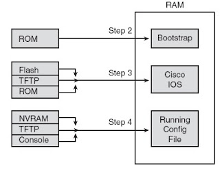
Router (or switch ) has 3 kind of memory :
  • ROM
  • FLASH
  • NVRam (none Available Ram) : hold the router and switch configuration file.
  1. When you turn your device on , first a POST (Power on self test ) is run then bootstrap file is run from ROM .
  2. Bootstrap looks and loads IOS from flash . (IOS is in order place in : Flash , TFTP server , RAM )
  3. Device copy satrtup.config from NVRAM to RAM

How a Router Chooses Which OS to Load :

A router chooses the OS to load based on the low-order 4 bits in the configuration register
and the details configured in any boot system global configuration commands found in
the startup-config file. The low-order 4 bits (the 4th hex digit) in the configuration register
are called the boot field, with the value of these bits being the first value a router examines
when choosing which OS to try and load. The boot field’s value when the router is powered
on or reloaded tells the router how to proceed with choosing which OS to load.
The process to choose which OS to load, on more modern routers that do not have
an RxBoot OS, happens as follows (note that “boot” refers to the boot field in the
configuration register):

  • Step 1 : If boot field = 0, use the ROMMON OS.
  • Step 2 :If boot field = 1, load the first IOS file found in Flash memory.
  • Step 3 : If boot field = 2-F:
  • a. Try each boot system command in the startup-config file, in order, until one works.
  • b. If none of the boot system commands work, load the first IOS file found in Flash memory.

NOTE On most Cisco routers, the default configuration register setting is
hexadecimal 2102.
NOTE Cisco represents hexadecimal values by preceding the hex digit(s) with 0x—for
example, 0xA would mean a single hex digit A.


Saturday, September 19, 2009

IP addresses :

IP Addresses


Current challenges in IP Addressing

An IP address consists of a 32-bit number with two components: a network address and a node.


The incredible growth of the Internet has resulted in following challenges:

  • IP address exhaustion
  • Routing table growth and manageability


IP Addressing Solutions

Solutions have been developed to slow the depletion of IP addresses and to reduce the number of

Internet route table entries by enabling more hierarchical layers in an IP address.


These solutions include the following:

  • Subnet masking
  • Address allocation for private internets
  • Network Address Translation (NAT)
  • Hierarchical addressing
  • Variable-length subnet masks (VLSMs)
  • Route summarization
  • Classless Interdomain Routing (CIDR)
  • Hierarchical Addressing
  • The benefits of hierarchical addressing are:
  • Reduced number of routing table entries
  • Efficient allocation of addresses

Variable Length Subnet Masks

The VLSMs are commonly used to maximize the number of possible addresses available for a

network. The benefits if VLSMs are:

Even more efficient use of IP addresses

Greater capability to use route summarization


Route Summarization

Route summarization can reduce the number of routes that a router must maintain because it is a

method of representing a series of network numbers in a single summary address.


Cisco routers manage route summarization in two ways:

Sending route summaries

Selecting routes from route summaries


CIDR

CIDR is a mechanism developed to help alleviate the problem of exhaustion of IP addresses and

growth of routing tables.

Redistribution Implementation Guidelines

Be familiar with your network and your network traffic

Do not overlap routing protocols

One-way redistribution

Two-way redistribution


NAT

Network Address Translation can be used to merge two large networks without having to readdress

the whole network. Another function of NAT is overloading inside global addresses.

This process allows several inside addresses to use a single IP address. NAT can also use a pool

of addresses or multiple interfaces.

Monday, September 14, 2009

ARP

What is ARP and how is it work ?

ARP :

As we know in OSI model when data need to send to network its necessary to encapsulated in frames to passing over network .

In layer 4 TCP/UDP headers adds on it and Segment was created . then it passed to layer 3 to add source and destination IP address and Packet is made .after , its need to encapsulate to frame and add Ethernet header and trailer on packet .in this step Frame is made.

you know for sending data , network protocol need source and destination IP address with source and destination mac-address . usually source and destination IP address are define , additionally source Mac-address is define too . so we need know destination mac-address ? ARP is a layer 3 protocol could find mac-address based on knowing IP address .
ARP request is a broadcast request that sends its request to all of hosts in the network with specified IP address to fined specified mac-address .
from example like below figure if HOST A want to send data to host B ,host A need to know host B IP address and mac-address to . if host A doesn't know(host A first check its ARP table ) host B IP address sends a request to host B and ask it's IP address . (DNS is a protocol that find IP-address based on name) .When host A find host B IP address its necessary to know host B mac-address too . so sends a request to host B to find its mac-address . and ARP do this step .
ARP results saves in a table called ARP cash . ARP cash include IP-address and mac-address of each device(host).this is a ARP cash :

X:\>arp -a

Interface: 192.168.0.31 --- 0x2
Internet Address Physical Address Type
192.168.0.1 00-30-48-53-71-51 dynamic
192.168.0.3 00-30-48-2a-75-bc dynamic
192.168.0.4 00-30-48-80-60-4a dynamic
192.168.0.98 00-0c-f1-6c-55-c7 dynamic
192.168.0.108 00-18-37-05-5b-07 dynamic
192.168.0.121 00-1a-80-4a-5a-cb dynamic
192.168.0.127 00-13-e8-da-d8-0b dynamic

  • use arp -a on your windows base PC or show ip arp cammand on your router to see ARP cash.
  • ARP protocol for each ARP request first check ARP cash and if cant find any thing , then send the request with source and destination mac-address with : 00:00:00:00:00:00 (6 bytes) and Ethernet destination field is : ff:ff:ff:ff:ff:ff (6 bytes) for broadcasting.
  • If destination host is not on a same subnet with source host then the ARP request send to default gateway .with source mac-address and default gateway mac-address for destination field and destination IP address .
  • hosts need to use ARP only once in a while (why ?)
Proxy ARP :
Can help hosts on a subnet to reach remote subnets without configuring routing or a default Gateway.
Proxy Arp is a kind of ARP that runs on router .
imagine in your network you have more than 1 network IP-address so you should use a router to route your packets and data to each other . .if your router is fail down what happens ? your requests to another network can't reach and cause a problem. if you run Proxy ARP on your router , the router pass arp-cash to all over the hosts in a network and each host can find many mac-address of the other devices as soon as possible in it's own arp-cash.
  • using Proxy ARP will definitely increase the amount of traffic on your network segment , and hosts will have a larger ARP table used to handle all the ip-to-mac address mapping .
  • Proxy ARP is configured on all Cisco routers.
  • You can instead HSRP (Hot standby router Protocol) with Proxy ARP .
  • Proxy ARP isn't realy separet protocol. its a service run by routers on behalf of other device such as PCs that are separated from others by a router.

IARP : (Inverse ARP) works like ARP but it maps the DLCI to IP address in a frame-relay

AARP : (Appletalk ARP) . the protocol in an appletalk that maps datalink adderss to network address.

Sunday, September 13, 2009

NAT

NAT (Network Address Translation)

"Nat" in simple words !

In summary NAT has one important goal : Extend IP address space by translate private IP address to public IP address .

Obviously remember that IP ver 4 is not enough to use for anyone who want connect to internet .so its important to manage the use of IP address in the world by any way to prevent wasting IP addresses.

Network engineers in the world define 3 standards to manage IP address for avoid IP Address wasting :
  1. CIDR(Classless Inter domain Routing )
  2. Private addressing
  3. NAT

Memorize these notes for NAT :
  • NAT technique that use IP v4 address through a public-to-private .
  • NAT hide your network from Internet view.
  • NAT is configured on a device such as router on edge between private network and public network (Internet )
  • Because of NAT typically resides in a boundry router between private and public network cant function with "IP sec" ( the popular encryption technology for VPN . because IP sec requires trace end to end handshaking in other to setup initial encryption rules . and IP sec packets can't be modified or recognized by NAT )
  • NAT = translate private IP address (invalid) to public IP address(valid) .
  • NAT build NAT-table , a heart of nat working .if any connection is disconnected the registered field is removed from NAT-table .
  • Any NAT process need 160 bytes memory . so if 1000 nat process occurred , means NAT need 1.6 Mb of memory .
  • Because of connecting to internet using only a registered network number .

Ok ! lets talk about " How NAT works ?"


NAT resides in a router in edge of your network and internet . below figures show how NAT do and how NAT-table is complete.

  • In cisco terminology NAT devide network in 2 parts. Inside and Outside. each of them have two sides . local and global . you can see them in below figures .
  • Inside Local : Your private IP address and Hosts in your network , all of them inn inside local.
  • Outside Local : Default gateway IP address .(Routers interface that connected to your LAN)
  • Inside Global : routers interface public IP address that connected to internet .
  • Outside Global : Public IP address of internet .
  • Actually NAT translate inside local IP address to outside global IP address by changing source and destination IP address in received packets.


NAT works in 3 terms :
  1. Static NAT :
  2. one-to-one mapping address between inside local and inside global . for example one host need to connect to internet and a router do that by map its private IP to public IP address.
  3. for each connected device in NAT-table a new record is registered and if disconnected the record is removed .
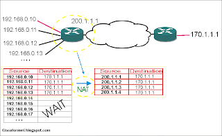
  4. In static NAT if more than one private IP address need to connect to internet in needs the same quantity public IP address . (This is a big problem for static NAT )
  5. Look at below figure :

  • in this picture as you see for each private ip Address need same as quantity public IP address . imagine that if hundreds of hosts want toi connect internet how much public ip address we need ? is it possible?!..


2. Dynamic NAT :

  • Dynamic NAT have some difference from static NAT . both of them mapping private-to-public IP address (or reverse). but dynamic NAT setup a pool of possible inside global IP address that match with any request to router to connect to internet .
  • NAT can be configured with more IP addresses in the inside local address list than in the
    inside global address pool. The router allocates addresses from the pool until all are
    allocated. If a new packet arrives from yet another inside host, and it needs a NAT entry, but all the pooled IP addresses are in use, the router simply discards the packet. The user must try again until a NAT entry times out, at which point the NAT function works for the next host that sends a packet. Essentially, the inside global pool of addresses needs to be as large as the maximum number of concurrent hosts that need to use the Internet at the
  • same time—unless you use PAT, as is explained in the next section
  • you can manually clear the table with this statement : #clear ip nat tranlateion

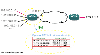
3.Overloading NAT by PAT (Port address translation)
  • as you see in real world if hundreds or thouseneds of hosts need to communicate with internet last 2 kind of NAT don't useful. and another way is necessary .
  • PAT solves the nat overlapping and allows NAT to scale to suport many clients with only a few public ip address.
  • with PAT router can accept all of request and do like this : make a packet with source address of inside global IP-address with differenet port numbers for different host IPs (local inside IP-address)
  • because of each port need 16 bits so can use more than 65000 port .
  • the dynamic entry still in the table as traffic flows occasionally.
  • When PAT creates the dynamic mapping it selects not only an inside global address but also a unique port number to use with that address .
  • actually both of Static and dynamic NAT translate one-to-one mapping in other side PAT use port numbers and significantly reduce the number of required registered ip address .
4-Overloading NAT :

  • if one company uses public IP addresses instead of private ip address then this company with thease ip address to conncting internet have some problems. because of using public ip addrees that means these ip addresses sets more then one once.
  • in below figure as you can see hosts in inside network uses IP addresses with network of 170.1.1.0/24 . so if host A want to ping or send a request to cisco.com , the request is sent to router then router forward it to 170.1.1.1 a host in that LAN. to solve this problem we should config Overlapping NAT on router . so router can mapping source and destination IP address . how ? first host A send a DNS request for cisco.com NAT router resolve DNS request and maps cisco.com ip address (170.1.1.1) with outside local IP address of his E0/0 ip address , 192.168.0.1 . then host A thoughts that the cisco.com ip address is 192.168.0.1 and send his all request to this ip address. look at below figure to NAT table to better understanding .

Normal 0 false false false EN-US X-NONE AR-SA MicrosoftInternetExplorer4

NAT Configuration :

Static NAT Configuration :

1. On interface that connect to LAN (Local outside interface ) : #ip nat inside

2. On interface that connect to WAN (Global inside interface ) : #ip nat outside

3. # ip nat inside source static private-address public-address

R1(config)#ip nat inside source static 192.168.0.10 85.198.0.1

4. # ip nat inside source static port private-address port-number public-address port-number

R1(config) #ip nat inside source static tcp 192.168.0.4 25 85.198.0.1 25

R1(config)#ip nat inside source static udp 192.168.0.1 53 85.198.0.1 53

5. #show ip nat statics :

R1#show ip nat statistics

Total active translations: 3 (3 static, 0 dynamic; 2 extended)

Outside interfaces:

FastEthernet0/1

Inside interfaces:

FastEthernet0/0

Hits: 0 Misses: 0

Expired translations: 0

Dynamic mappings:

6. #show ip nat translation :

R1#show ip nat translations

Pro Inside global Inside local Outside local Outside global

--- 85.198.0.1 192.168.0.10 --- ---

Tcp 85.198.0.1:25 192.168.0.4:25 --- ---

udp 85.198.0.1:53 192.168.0.1:53 --- ---

Dynamic NAT Configuration :

1. On interface that connect to LAN (Local outside interface ) : #ip nat inside

2. On interface that connect to WAN (Global inside interface ) : #ip nat outside

3. Making pool on inside global interface of router :

#ip nat pool pool-name start-network end-network netmask

Router(config)#ip nat pool network1 85.198.0.1 85.198.0.5 netmask 255.255.255.248

4. Making access-list to make a a list of allowable ip-address to access internet :

#access-list statndard-no permit network wildcard-mask

Router(config)#access-list 50 permit 192.168.0.0 0.0.0.255

5. #ip nat inside source list access-list-no pool pool-name

Router(config)#ip nat inside source list 50 pool network1

7. #show ip nat statics :

Router#show ip nat statistics

Total active translations: 0 (0 static, 0 dynamic; 0 extended)

Outside interfaces:

FastEthernet0/0

Inside interfaces:

FastEthernet0/1

Hits: 0 Misses: 0

Expired translations: 0

Dynamic mappings:

-- Inside Source

[Id: 1] access-list 50 pool network1 refcount 0

pool network1: netmask 255.255.255.248

start 85.198.0.1 end 85.198.0.5

type generic, total addresses 5, allocated 0 (0%), misses 0

Overloading NAT ( PAT ) Configuration :

1. On interface that connect to LAN (Local outside interface ) : #ip nat inside

2. On interface that connect to WAN (Global inside interface ) : #ip nat outside

3. #access-list statndard-no permit network wildcard-mask

Router(config)#access-list 50 permit 192.168.0.0 0.0.0.255

4. #ip nat inside source list access-list-no interface interface-name overload

Router(config)#ip nat inside source list 50 interface fastEthernet 0/0 overload

5. #show ip nat statics

Router#show ip nat

*Mar 1 00:07:41.463: %SYS-5-CONFIG_I: Configured from console by console

Router#show ip nat st

Router#show ip nat statistics

Total active translations: 0 (0 static, 0 dynamic; 0 extended)

Outside interfaces:

FastEthernet0/0

Inside interfaces:

FastEthernet0/1

Hits: 0 Misses: 0

Expired translations: 0

Dynamic mappings:

-- Inside Source

[Id: 1] access-list 50 interface FastEthernet0/0 refcount 0